穆谱社区

Trends in Mössbauer Spectrometer Designs

The following article was published in the Volume 28, Number 10 (December 2005) issue of the Mössbauer Effect Reference and Data Journal.


Trends in Mössbauer Spectrometer Designs    

Sobir M. Irkaev
Institute for Analytical Instrumentation, Russian Academy of Sciences
26 Rizhski Avenue
St. Petersburg, 190103 RUSSIA
e-mail: sobir_irkaev@mail.ru

Some newly discovered effects lose their glamour after a short period of euphories; others, however, retain their fascination for a long time and, even as they mature, display unexpected features. The Mössbauer effect belongs to the second category….    

Hans Frauenfelder

Introduction

The state of the art in the field of Mössbauer spectrometer design is here considered. In this paper, we do not mention the questions connected with laboratory technique (the temperature or pressure chambers, the systems creating external electrical or magnetic fields, and detection devices that use any kind of electron spectrometer) or the developing field of synchrotron Mössbauer spectrometry, where the most attractive opportunities of the Mössbauer effect and synchrotron radiation are incorporated and a special mathematics is created.

It is necessary to note that the technical image of the modern Mössbauer spectrometer has developed, in the core, owing to works by E. Kankeleit, T. E. Cranshaw, J. J. Spijkerman, R. L. Cohen, G. K. Wertheim, N. Benzer-Koller, R. H. Herber, F. E. Wagner, G. M. Kalvius, V. V. Sklyarevskii, A. L. Kholmetskii, G. Klingelhöfer, and many others. These are described in more detail in reviews and books on the equipment and procedure of Mössbauer spectrometry [1-5].

1. Design of the Mössbauer Spectrometer

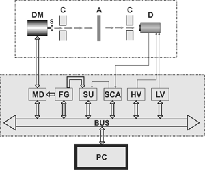
A Mössbauer spectrometer consists of an analytical bench (or cabinet) and control, energy selection, and storage systems interfaced to a personal computer.

The analytical cabinet includes vibro-damping and a carrier platform, a Doppler modulator (DM), a gamma ray detector with built-in preamplifier (D), and guard and shielding collimators (C). The electronic part consists of the Doppler modulation system, the data storage and processing system, and the control devices.

Control, energy selection, and storage systems, together with necessary equipment, consist of: a function generator (FG), modulator drivers (MD), a discriminator with built-in amplifier (single channel analyzer) (SCA), storage units (SU), a low voltage power stabilizer unit (LV), a high voltage power supply (HV), and a personal computer. Energy selection and storage systems may be performed in CAMAC, NIM, or Computer Technology.

                              Figure 1. Block-diagram of a Mössbauer spectrometer.        
In the Mössbauer spectrometer shown in Figure 1, the radioactive source S (or absorber) is attached to the moving part of the Doppler modulator. The function generator (FG) provides start and memory (channel) advance pulses for the synchronization of the entire system; these pulses are then fed to the storage units (SU). Modulator drivers (MD) produce the control voltage signals for the Doppler modulator (DM), thus making it vibrate according to the preset law of motion. After passing through the absorber, gamma-quanta are recorded by the detector (D). The electric output signals of the detector are received by the preamplifier. The preamplifier, which is located in the detector housing, converts the charge pulse of the detector to voltage and provides matching between detector output and SCA input.

After amplification and shaping of the detector signal, the pulses from the preamplifier are sent to the input of the SCA with built-in amplifier. The amplitude selected and normalized pulses from SCA output are fed for counting to the information input of the SU. The exact matching of the working part of the moving cycles with the channel of the SU is provided by start and channel advance pulses from the FG. High voltage for the detector is provided by the HV (bias) and the stabilized voltages for preamplifiers are supplied by the LV. The counting cycle begins with the arrival of a starting pulse and stops after channel advance pulses have passed. During accumulation, the spectrum can be forwarded to the monitor of a computer using the main program.

The global characteristics of a Mössbauer spectrometer are velocity range, velocity mode, velocity linearity, velocity time and temperature stability, velocity reproducibility, number of channels, channel capacity, and dead time of the storage system.

The velocity range of ±100 mm/s is optimum for a serial Mössbauer spectrometer, as a greater velocity range is required for only four isotopes (237Np, 169Tm, 161Dy, and 238U), seldom applied in experiments. Linearity of a velocity scale of a spectrometer is the most important parameter, as it defines the quantitative values of parameters of the hyperfine interactions in the sample under investigation. The best spectrometer should provide nonlinearity of less than 0.1%. As, depending on the requirements and tasks of the experiment, it is necessary to apply various laws of velocity – rectangular, triangular, trapezoidal, sinusoidal – it is necessary to consider as the best solution the opportunity of the assignment of a mode of velocity. Time and temperature stability of spectrometer operation is necessary because some experiments continue for a long period of time (from one day to about a month), and this quantity should not exceed an error of defined parameters. The reproducibility of velocity means that we can receive the same value of parameters of a spectrometer at each new switch. This value usually has a quantity ±0.01%. The number and capacity of channels of accumulation are determined by the complexity of the Mössbauer spectrum of the sample. The modern spectrometer should provide a variable number of channels, for example, 128, 256, 512, 1024, and capacity within the limits of 1024-1 pulses.

2. The Doppler Modulation System

Because the system of Doppler modulation is a specific unit proper only in Mössbauer spectrometers, we shall examine this system in more detail.

The Doppler modulation system defines the quality of an abscissa axis of a resonant spectrum. It includes the Doppler modulator (velocity transducer) and a control system (the modulator driver). Various ways of scanning (temperature, gravitational, magnetic, ultrasonic) have been offered, but the most convenient and simple use of the linear Doppler effect has appeared. This technique was offered by R. Mössbauer, and all modern spectrometers have the same logical circuit as the one in our founder’s first laboratory set-up.

2.1. Doppler Modulator (DM)

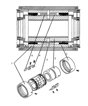
Devices for Doppler modulation using rotating disks, screws, cams, hydraulic mechanisms, etc., have been offered, but the most convenient has appeared to be electrodynamic systems. The calculations in [6] have been shown to lead to the most successful construction of a Doppler modulator (velocity transducer), suggested by E. Kankelait [7]. Construction has been advanced by U. Klein [8]. In [9], the precision Doppler modulator, which comprises advantages of these modulators, is described. The main advantages of the suggested transducer come from using rare earth magnets and including some irregularities in the construction of moving parts, which scatter the acoustic waves in the material of the parts (Figure 2).

The permanent rare earth magnets form the exterior surface of the working gap. When the permanent magnets are arranged in such a manner, the magnetic field is concentrated in the working gap (more than 0.4 T) and the dissipative magnetic field on the surface of the transducer is less than 0.002 T.


Figure 2. Doppler modulator, cross-sectional view, and the magnetic systems assembly, consisting of: (1) external magnetic field conductor with permanent magnets attached by epoxy glue; (2) internal magnetic field conductors on centered cylinder; (3) drive tube with coils; (4) aligning segments.

Furthermore, this construction of a magnet system led us to decrease the distance between pick-up and drive coils (70 mm) and makes the mechanical bond of the coils more rigid.

The drive tube is made of aluminum-magnesium alloy. High frequency resonances are dumped by some irregularities (holes, slots, and differences in thickness) in the geometry shape of the drive tube and other moving parts. The introduced irregularities split the acoustic wave started from one edge of the moving part, and the partial waves reach the opposite edge with different phases suppressing each other. On the ends of the drive tube the drive coil (140 turns of 0.22 mm diameter copper wire) and pick-up coil (650 turns of 0.06 mm diameter copper wire) are arranged. The resistance of the drive coil is 11 Ohm, and the resistance of the pickup coil is 650 Ohm.

Flat springs are made of beryllium bronze, 0.4 mm in thickness. Metal springs allow us to move weight up to 200 g (resonance detectors, scattering samples, etc.) and work for a long time at high velocities (more than 150 mm/s). Oscillations of metal spring elements are effectively dumped by a cover of polymer resin.

2.2. Modulator Driver (Servosystem)

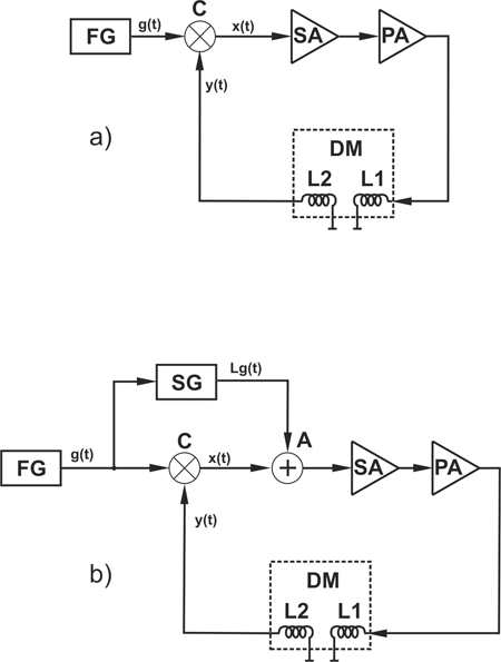
The first Doppler modulation system of the electrodynamic type consisted of the reference signal generator and a power amplifier. Absence of a chain of negative feedback led to the impossibility of achieving the demanded precision of reproducibility of the given law of motion because of inertial properties of the Doppler modulator and the strong influence of exterior perturbing factors (vibrations, ultrasonic and electric noise). The nonlinearity for these systems, as a rule, exceeded 1%.

                             
Figure 3. Doppler modulation system: (a) feedback velocity control, and (b) combined velocity control. FG – functional generator, C – comparator, SA – error signal amplifier, PA – power amplifier, A – analog adder, SG – Lg(t) signals generator, DM – Doppler modulator, L                               1 – drive coil, L                               2 – pick up coil, g(t) – reference signal, x(t) – error signal, y(t) – pick-up coil signal.

Later, such a system was replaced by systems with negative feedback. Thus, on drive coil L1 of the Doppler modulator an amplitude and power amplified error signal are fed, where error x(t) is equal to the difference between a reference signal g(t) and a signal of velocity from pick-up coil L2 of the Doppler modulator (Figure 3a): x(t) = g(t) – y(t). The maximum attainable velocity precision with a backup loop is limited by the self-excitation stability condition and, as usual, the value of nonlinearity is not better than 0.1%.

The velocity scale linearity may be improved by adding to the error signal the signal x'(t), which is the result of action of some functional L on a reference signal g(t) (Figure 3b): x'(t) = x(t) + Lg(t), and the real form of functional L is defined by dynamic properties of the Doppler modulator. Such approach enhances velocity linearity. Further increase in the precision (highly desirable, for example, in selective excitation double Mössbauer effect experiments) is limited because the real Doppler modulator characteristics deviate from those of an “ideal” modulator. This demand, involving higher derivatives of the reference signal into the drive system, is difficult to realize in practice. Furthermore, a disadvantage of the modulation system of that type is the need for amplitude adjustment of the components, which are added together with error signal any time the amount of load on the moving parts of the Doppler modulator or frequency of the reference signal are changed.

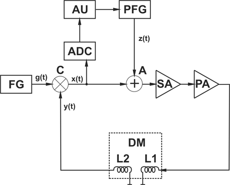
The alternative approach to the problem of enhancing linearity of a velocity scale consists in the use of an additional signal synthesized by processing of an error signal [10]. The procedure for utilization of this method is as follows: at the zero z(t) signal, the error signal x0(t) is measured over several Doppler modulator vibration cycles. By its averaging using the formula

  (1)

(where T is the DM vibration period, and N is the number of vibration cycles over which the error signal x0(t) is averaged; in practice, the N value may be assumed to be 100), the signal z(t) is determined and then used as an additional control signal which is added to the error signal x(t). As a result, the regular component of the error signal x(t) is removed.

                             
Figure 4. Doppler modulation system with an additional control signal. FG – functional generator, C – comparator, SA – error signal amplifier, PA – power amplifier, A – analog adder, ADC - analog-to-digital converter, AU – arithmetic unit, PFG – programmable FG of the additional control signal, DM – Doppler modulator, g(t) – reference signal, x(t) – error signal, y(t) – pick-up coil signal, z(t) - the additional control signal.

The block diagram of a velocity transducer control system that implements the above technique is given in Figure 4. The reference signal g(t) from FG is fed into the comparator (C), which generates the error signal x(t) = g(t) – y(t), where y(t) is the velocity signal applied to the second input of comparator from pick-up coil L2 of DM. The error signal x(t) is fed to the first input of the adder (A), to whose second input the signal z(t) is delivered, which is zero for the first several cycles after instrument power switch-on. The output from adder (A), after the amplitude amplification in amplifier SA via power amplifier PA, is fed into driving coil L1 of DM; that closes the feedback loop through a rigid shaft mechanically coupling coils L1 and L2. On termination of transients caused by instrument switch-on, the additional control signal z(t) path starts its operation. The error signal x(t), digitized by the analog-to-digital converter (ADC), is utilized by the arithmetic unit (AU) to compute the signal z(t) digital representation array according to Equation (1). This array is loaded into buffer RAM of the programmable function generator (PFG) and used to generate the analog signal z(t). Thus, the optimal adjustment procedure of the velocity transducer system is performed automatically.

As reference signal generator FG, a programmable function generator on the base of a 4KX12 RAM and a digital-to-analog converter were used. The FG allows any desired motion law to be generated, and this extends substantially the application area of the Doppler modulation system since, along with the standard modulation law in the form of a symmetrical triangle with smoothed vertices, it is possible to work in a constant velocity mode, necessary to compensate the isomer shifts of untuned pairs (source-resonance converter), in a “region of interest” mode using a trapezoidal reference signal, or in a sinusoidal reference signal mode, needed in experiments using cryostats where the mechanical link modulator’s shaft-specimen is much longer, etc.

The digitized error signal from the ADC output is fed via the bus into a personal computer used as arithmetic unit (AU). The computer averages the error signal according to Equation (1) and loads the result via the bus into the buffer RAM of the programmable function generator (PFG) of the same structure as reference signal FG.

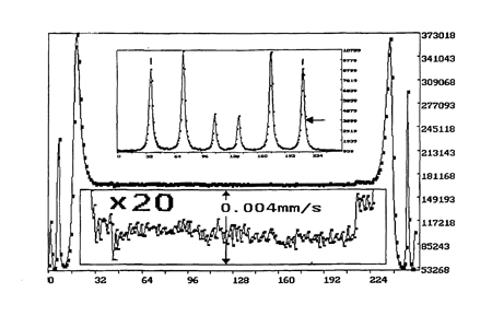
To determine the velocity precision, the following experiment was carried out. In the constant velocity mode, the Doppler modulation system was adjusted for the maximum outer slope of the extreme line in the hyperfine spectra of α-Fe foil enriched to 90% that was placed into the volume of the resonance detector (Figure 5). In this case, even slight velocity deviations from a preset value lead to an essential change in the detector pulse count rate. The results of this experiment have shown that the spectrometer exhibits constant velocity precision within 1 µ/s per operating cycle, corresponding to a relative error of motion law reproduction of at least 0.02%.

                             
Figure 5. Results of test experiment.


Lines No.

1

2

3

4

5

6

Pi, mm/s

-5.3122

-3.0782

-0.8362

0.8372

3.0792

5.3122

Γi, mm/s

0.2074

0.2835

0.1637

0.1527

0.1965

0.2104

The table above gives the results (positions Pi and line width Γi) obtained on a metallic iron standard sample in a measurement made with double Doppler modulation systems and adjustment to the inner line of the resonance detector with the up-to-90% enriched metallic iron foil as its converter. As seen from the table, the average width of the inner lines of a metallic iron Mössbauer spectrum is equal to (0.158±0.007) mm/s, against (0.220±0.007) mm/s as obtained in the conventional mode.

3. The Gamma-Ray Counters and Energy Selection System

The well-known single channel nuclear spectrometer of ionizing radiation is used as a recording system of gamma rays in the Mössbauer spectrometer. It includes a detector, preamplifier, amplifier, single channel analyzer, and high voltage power supply.

The choice of a particular detector depends primarily upon the gamma energy range of interest. The detector must have sufficient material to absorb a large fraction of the gamma ray energy. The higher energies are more effectively absorbed by higher Z materials. Other parameters are count rate capability, resolution, and, for timing experiment applications, pulse rise time. Registration can be spent both on full-energy peak (photo-peak) and escape peak.

The kinds of detectors used in a Mössbauer spectrometer can be categorized as gas-proportional, scintillation, semiconductor, and resonance counter.

Gas-proportional detectors are used for low energy (in the range 1-30 keV) gamma rays. As a gas admixture, Ar, Kr, Xe with CO2, and CH4 (about 10%) are commonly employed.

Scintillation detectors may be used in low and high-energy gamma rays. It consists of a photomultiplier tube to convert the light scintillation pulse into an electric pulse. Solid crystals such as NaJ(Tl) or, when we deal with fast count rate experiments YAlO3(Ce), are used.

Semiconductor detectors, consisting of large crystals of, for example, very pure germanium or silicon, in which minor crystal defects or impurities may be compensated for by lithium, have superior energy resolution and are applied in the low energy range.

The resonance detectors have a selective sensitivity to resonance gamma rays and consequently a unique resolution. The discriminating efficiency of resonance detectors is due to the fact that the resonant absorption effect is used in the detection process. Resonance absorbers, called converters, are actually placed inside the detector volume.

As a registration volume, any of the above detectors are used.

The scintillation detectors have high efficiency and high-speed response, the semiconductor detectors possess the best energy resolution, and the gas proportional detectors have the most successful combination of high count rate and energy resolution.

When we choose the type of the detector, we should take into consideration the energy spectrum of the parent source nuclei, the resonance radiation energy value, the source activity, and we also should know if there are some additional gamma or X-ray radiations near the resonance radiation.

We can divide the various Mössbauer isotopes into types according to the choice of the best detector. Of course, there are overlapping regions where one can use both, e.g., the semiconductor and the gas proportional detectors. Then the final choice of the detector depends on financial support.

For example, when we deal with 57Fe isotope experiments, we can use gas proportional (Xe or Kr filled) or scintillation detectors (thickness of crystals – 0.1 mm and 0.35 mm for NaJ(Tl) or YAlO3(Ce), respectively); for 151Eu and 197Au we can use the semiconductor detector; and for 119mSn, the scintillation (thickness of crystal – 1 mm) or the semiconductor detector. Nevertheless, for 121Sb and 125Te recording on photo peak, we should use the semiconductor detector or, if we apply proportional or scintillation detectors, we should record escape peak.

Some more words about newer generation semiconductor detectors – the thermo-electrically (by single stage Peltier element) cooled silicon drift detector (SDD) and the Si-PIN diode. SDDs have excellent resolution (<160 eV for energy 5.9 keV) and count rate up to several ten thousand counts per second, but small sensitivity (typically 5 mm2). Resolution of SDDs can already be compared to that of Si(Li) or Ge detectors requiring expensive and inconvenient liquid nitrogen cooling. The Si-PIN diode has a bigger sensitivity area (up to 20 mm2), and for low count shape (about 20 kcpc) the resolution is about 190 eV.

Any type of detector transforms the gamma-quanta energy into the charge pulse signal.

The preamplifier, commonly located in the detector housing, serves for the conversion of charge pulse to voltage, signal amplification, pulse shaping, and providing a match between the high impedance of the detector from one side and the low impedance of coaxial cables to the amplifier from the other. The amplifier provides linear amplification of the pulse signal. The single channel analyzer (differential discriminator) serves for selection of electric signals by the amplitude.

The ultimate result of this chain of devices is the flux of the electric pulses of the standard amplitude and shape, corresponding to the resonance radiation intensity in the total radiation flux, reaching the detector.

However, this correspondence, as of many measurements, is subjected to systematic and statistical errors that affect the measured Mössbauer spectrum. The perfect recording system should possess maximum recording efficiency, high-energy resolution capability, low noise level, and minimum “dead” time of recording (high count rate stability). These parameters should not depend on external disturbance, entering radiation intensity and the type of the isotope under investigation.

The demand of high-count rate without a loss of resolution significantly complicates recording schemes for any detector type, not speaking of semiconductor detectors. In such cases, a linear amplifier is designed by a two-channel scheme of fast-slow amplification. At the amplifier input, pole-zero cancellation and amplitude overload recovery schemes are introduced.

This arsenal of electronic engineering is used for reducing errors in the Mössbauer spectrum and for saving the measurement time.

4. The Data Storage and the Data Processing Systems

The process of receiving the data concerning the sample under investigation with the aid of Mössbauer spectrometry includes two parts:

  1. The measurement of the distribution of the number of gamma-quanta transmitted through the sample or scattered by it as a function of the energy of gamma-quanta – it is made with the help of a spectrum storing electronic system, and

  2. The mathematical treatment of this distribution, which consists of the adjustment of the parameters of the physical model to the measured spectra by the least squares technique – this adjustment is carried out on a computer.

The spectrum storing system has evolved substantially since the discovery of the Mössbauer effect. In the beginning, multichannel analyzers were used as the device for storage of the incoming information.

The process of data receiving was divided into parts. The spectrum measured by the multichannel analyzer was brought on the intermediate data carrier and then fed into a computer for data processing. Later on, with the appearance of rather cheap and effective mini-, micro-, and personal computers, the measurement of the experimental spectra and data processing were brought close together, and the question of the optimum function distribution between a computer and the electronic part of the spectrometer arose.

It is known that there are four main techniques of computer-aided data acquisition:

  • Polling of readiness,

  • Program interruption,

  • Direct access to the computer memory, and

  • Using an autonomous controller with buffer memory as an accumulator.

Experimental data collection operating in the polling of readiness mode needs the minimum expenditure for design and manufacture of auxiliary equipment, but it occupies the processor 100% by routine operations of the polling of readiness and data transfer.

The program interruption mode demands more interface complexity, but frees the computer processor of external device polling of readiness and gives it the possibility of performing the data processing simultaneously with the data accumulation. It is necessary to note that when the frequency of entering external service inquiry requests increases, the computer effectiveness lowers, gradually approaching 100% occupation by data transfer operations.

The next step on the way to releasing the processor from data storage operations is to use the direct access to the computer memory mode. From the point of view of the programmer, the data “themselves” are co-accumulated in some array, situated in the address space of random access memory (RAM). When compared to the above-mentioned methods of data storage, the direct memory access mode is most effective from the processor viewpoint. The shortcoming of this mode is that of fixing a RAM region for data storage, which leads to limitation of computer operation. Moreover, the processor effectiveness (fast-response) is reduced, since it has to share the channel with a direct computer memory access device.

It is shown in [11] that the most rational way of data storage from the viewpoint of effective computer use is to employ a special-purpose accumulator controlled by the computer. The accumulator performs the functions of collecting and accumulating the information in its buffer memory, and the computer accomplishes only general control of the accumulator (switches accumulation on and off, cleans the buffer memory, transfers the data from the buffer memory to RAM after a spectrum accumulation). The use of the special-purpose accumulator frees all computer resources and provides for the minimum time of service request processing.

5. Velocity Calibration

This issue is one of the most important among all the others, because the precision and adequacy of the physical information extracted from the accumulated spectrum depends on the solution of this problem.

The main part of the Mössbauer spectrometer is the Doppler modulation system. The value of the resonance effect is rather small; it means that there is no considerable change in the count rate – it doesn’t exceed the dynamic range of the spectrometer. That is why the shape of the Mössbauer spectrum and mainly the energy scale are defined by the characteristics of the Doppler modulation system.

The velocity scale for constant velocity spectrometers is derived in a straightforward manner. However, for velocity scanning spectrometers the situation is very complicated. In this case, we are to know the maximum velocity, the law of its change, and also the channel of zero velocity. We also have to know the real law of the velocity change, to recognize if it deviates from the preset one.

There are different ways to solve the problem of velocity calibration.

1. Measurements of Known Hyperfine Splitting Spectra. This method is definitely a secondary calibration method. Here we can use the magnetic hyperfine splitting spectrum of 57Fe resonance in metallic iron, which is known with good accuracy. If the source 57Co in a metallic iron matrix is used with metallic iron as the absorber, we obtain a spectrum consisting of 19 lines. That is displaced in the velocity range ~10 mm/s and is symmetrical with respect to the zero velocity. It allows us to obtain simultaneously the calibration constant and the position of zero velocity. Accuracy of calibration in this case may be obtained up to 0.1%.

However, for many Mössbauer resonances the range of the velocity measured by this method is very small. With a well-fabricated spectrometer giving the linear signal of the pick-up coil at large amplitudes, the velocity calibration could be extended up to 500 mm/s simply by comparison of the peak-up coil signal voltage with the reference signal. This calibration provides accuracy up to 1%.

For calibration of the velocity scale at high velocity and low temperatures in the range from 200 mm/s to 1000 mm/s, one can use the magnetic hyperfine spectrum of metallic 159Tm at 4.2 K.

2. Radiofrequency (RF) Modulation Technique. The source or the absorber is mounted on the piezoelectric crystal, which is excited by RF voltage of known frequency v. The single resonance line in this case produces side bands on resonances separated from each other by E = h v. That is, to recalculate this energy difference in the term of the velocity, it is necessary to know accurately the value of gamma-ray energy. It should be noted that for many applications the direct calibration of the spectrometer in the energy units, but not in a term of velocity, represents an important task.

3. The Optical Technique. This technique is based on searching the interferences or the Moiré fringes. Among interferometer methods, one can choose the Michelson interferometer with a moving mirror, which is attached on one leg of the moving part of the Doppler modulator. The fringes are recorded by photocell and their number is counted and accumulated in the storage device, like gamma ray counting in the real Mössbauer experiment. If we know the light wavelength value, the open state time of any channel (dwell time), and the number of memory scanning cycles, then we can define the velocity in each channel. However, a realization of this method causes some hindrance when very small or large velocities are calibrated.

The device using the Moiré fringes is based upon intensity modulation produced when light is passed through two gratings moving one relative to another. The variation of intensity is recorded, similar to the fringes produced in the interferometer method.

6. Some Unconventional Schemes

In all spectroscopic methods, the most important tasks are to achieve the theoretically predicted resolution and to expand the potentialities and fields of the application.

If the emission and absorption lines have a natural width, the experimental line width for a very thin absorber will go to its limit 2Γ0. However, when we deal with poorly resolved or unresolved spectra, for extraction of useful information it is necessary to narrow the spectrum line width. Is it possible to observe a Mössbauer spectrum with a narrower line width?

According to the Heisenberg uncertainty relation Γnat ≥ h/2πτ; therefore, it is clear that if we count gamma-quanta in a period of time, which is far beyond the mean lifetime, then we reach the higher resolution. However, for such experiments we must know the moment of the creation of the excited state in order to tune the recording system for the necessary time period. Sometimes we are lucky to have such a possibility.

Let us consider the case of the isotope 57Fe. In this case, as a source we commonly use in experiment the radioactive parent isotope 57Co, which decays due to beta-capture to the isomer 57Fe in the excited state. After the time τ = 8.7 nsec is passed, the “Mössbauer level” with the energy 14.4 keV appears. The recording of the gamma-quanta with the energy 123 keV means the creation of the 14.4 keV level.

Now we turn our attention to two other methods of line narrowing.

Mitrofanov, et al. [12] have proposed a new type of detector. The substance having the resonance absorption (converter) is put into the detector volume and the recording of secondary radiation created in the converter is performed (resonance detector). The final limitations here are shown by numerical calculation Γexp = 1,47Γ0.

There is one more advantage of the resonance detector over ordinary detectors. In the transmission mode experiment, they allow the value of the Mössbauer effect to be increased considerably. Furthermore, when we use the emission mode there is no need to use the analyzer and the value of the effect attains some hundreds percent. But here we should notice that the use of a resonance detector does not give the real narrowing of the source line width, but leads to the experimentally seen narrowing of the line. What features must the converter have?

It must have the line width of absorption that does not exceed the natural one, then a high value of Lamb-Mössbauer factor, and furthermore the line position of the converter in the energy scale must coincide exactly with the center of the source line. A small discrepancy leads to distortion of the experimental line shape and to the loss of recording efficiency, but a higher discrepancy (>>Γnat) makes the resonance melt into the background.

That is why we perform a laborious and unsuccessful, as a rule, search for the source-absorber “resonance pair.” In some institutes, for many years they have performed experiments to synthesize iron compounds, searching for a “resonance pair” for experiments with isotope 57Fe. To date, among all Mössbauer isotopes we can find only two effective resonance detectors – those for 119Sn and 151Eu experiments.

Andreeva and Kuzmin [13] have proposed another method of narrowing, consisting of filtration of the resonance line. For its realization, we should put between the source and the absorber a substance whose transmission spectrum has a doublet structure. The substance, used as a resonance filter, must also have a large value of Lamb-Mössbauer factor. Furthermore, it is necessary that the center of this doublet should coincide exactly with the center of the source line. Moreover, the value of quadrupole splitting (the distance between doublet lines) must have the optimum value. Numerical calculation showed that the best resonance filter must have the quadrupole splitting to Γ0 ratio in the range from 2 to 3.5, and the effective resonance filter thickness must not exceed Tf = 2.5, otherwise the filter will loose its narrowing effect.

Again, this method leads to searching for a filter substance. This problem is more difficult than in the case of a converter of resonance detector. To date, only the isotope 119mSn has a substance that can be used as a filter.

It should be noted that we could buy richer physical information; for example, a sign of hyperfine interactions if we deal with polarized radiation (circular or linear). In this case, we must prepare the source of polarized radiation and, for it, we must synthesize a suitable single crystal that has the radioactive nuclei, or find a filter-polarizer with the required characteristics.

As shown in [14-16], a universal solution to these problems is the introduction into the Mössbauer spectrometer scheme of additional systems of Doppler modulation strictly synchronized with each other. The selective excitation double Mössbauer effect spectrometer is a good example of the expansion of the potentialities of the technique [17-20]. For example, Mössbauer transmission spectra of goethite, substituted by aluminum, with the composition Fe(1-x)AlxOOH have a sextet with spectral lines that are often asymmetrically broadened, or with a predominant doublet. At interpretation of these spectra there are doubts as to the reason for the line broadening. Is the reason the dynamic processes caused by a paramagnetic relaxation, or is the broadening caused by distribution of static hyperfine interactions? For the solution to this problem, it is necessary to measure SEDM spectra.

Mössbauer spectra for two compositions (x = 8 mol % (a) and 2 mol % (b)), which measured in transmission mode (the upper spectra) and in geometry of the selective excitation of various sublevels of the sample under investigation are given in Figure 6. Arrows indicate which lines are excited. SEDM spectra unequivocally confirm the static, not dependent on time, distribution of hyperfine fields.

                                                           
Fig. 6. Mössbauer transmission and SEDM spectra of Fe                               (1-x)A                               lxOOH (x = 8 mol % (a) and 2 mol % (b)).

Other unconventional schemes for the Mössbauer spectrometer are described in [21].

7. Conclusion

The past years have been marked by strong progress in Mössbauer optics of synchrotron radiation. However, not each expert in the field of Mössbauer spectroscopy presumes to have to him or her self, in his or her laboratory, a source of synchrotron radiation. It is known that the basic properties of synchrotron radiation can be created in a laboratory. Pulsing character of radiation is shaped by means of resonant lockers [22]; polarization of radiation is created by application of the filter-polarizer [23]. There is hope to solve the problem of high intensity and the small angular divergence character of radiation by application of transporting and focusing lenses [24]. However, the best solution will be making a gamma-laser [25]. In search of it, undoubtedly, we will see progress in the development of new procedures and new schemes in Mössbauer spectrometers.

Boileau-Despreaux said: “Let’s hurry up! We are only passengers in the train of time. The moment I’m speaking in is already very far from me.”

References

  1. N. Benzer-Koller and R. H. Herber. “Experimental Methods.” In: V. I. Goldanskii and R. H. Herber (Eds.), Chemical Applications of Mössbauer Spectroscopy, New York/London: Academic Press (1968).

  2. S. M. Irkaev, R. N. Kuzmin, and A. A. Opalenko. Nuclear Gamma Resonance (Instrumentation and Techniques), Moscow: Moscow State University (1970), 207 pp.

  3. R. L. Cohen and G. K. Wertheim. “Experimental Methods in Mössbauer Spectroscopy.” In: Methods of Experimental Physics, Solid State Physics, Vol. 11, 307 (1974).

  4. G. K. Shenoy, F. E. Wagner, and G. M. Kalvius. “The Measurement of Isomer Shift.” In: G. K. Shenoy and F. E. Wagner (Eds.), Mössbauer Isomer Shifts (1978).

  5. E. Murad and J. Cashion. Mössbauer Spectroscopy of Enviromental Materials and Their Industrial Utilization, Kluwer Academic (2004).

  6. S. M. Irkaev and Yu. N. Maltsev. “Precision Doppler Modulator for Mössbauer Spectrometer.” Preprint No. 48. In: Multidimensional Parametric Mössbauer Spectrometry Instruments, Institute for Analytical Instrumentation (1991), 27 pp.

  7. E. Kankeleit. “Mössbauer Drives.” In: Proceedings of the International Conference on the Applications of the Mössbauer Effect, Jaipur, India, Indian National Science Academy, 143 (1982).

  8. U. Klein. “Mössbauer Spectrometer MSII (Velocity Transducer MA260).” Wissel GmbH.

  9. S. M. Irkaev, A. S. Kamzin, Yu. N. Maltsev, et al. “Intelligent System of Doppler Modulation.” Preprint No. 49. In: Multidimensional Parametric Mössbauer Spectrometry Instruments, Institute for Analytical Instrumentation (1991), 18 pp.

  10. S. M. Irkaev, A. S. Kamzin, Yu. N. Maltsev, et al. “Storage and Processing of Spectrometric Data.” Preprint No. 43. In: Multidimensional Parametric Mössbauer Spectrometry Instruments, Institute for Analytical Instrumentation (1990), 31 pp.

  11. S. M. Irkaev and Yu. N. Maltsev. Instr. Exp. Tech. 5, 182 (1995), “Precision Doppler Modulator for Mössbauer Spectrometer.”

  12. K. P. Mitrofanov, N. V. Illarionova, and V. S. Shpinel. Instr. Exp. Tech. 3, 49 (1993).

  13. M. A. Andreeva and R. N. Kuzmin. “Narrowing of the Mössbauer Lines.” In: Proceedings of the Conference on the Applications of the Mössbauer Effect (Tihany), 77 (1969).

  14. S. M. Irkaev, V. V. Kuprianov, V. A. Semionkin, and M. M. Sokolov. “Method of Gamma Resonance.” Copyright Certificate No. 1124714 (1982).

  15. S. M. Irkaev, V. V. Morozov, and M. M. Sokolov. “The Resonance Counter.” Copyright Certificate No. 896586 (1980).

  16. S. M. Irkaev, Yu. A. Baranov, and V. V. Morozov. “The Resonance Filter.” Copyright Certificate No. 896692 (1980).

  17. A. N. Artem’ev, G. V. Smirnov, and E. P. Stepanov. Sov. Phys. JETP 27, 547 (1968).

  18. W. Meisel. Monatsber. Deutschen Akd. Wiss. (Berlin) 11, 355 (1969).

  19. N. D. Heinman, J. C. Walker, and L. Pfeiffer. Phys. Rev. 184, 281 (1969).

  20. V. G. Semenov, S. M. Irkaev, and Yu. N. Maltsev. Nucl. Instr. Meth. B 95, 253 (1995).

  21. S. M. Irkaev. “Mössbauer Spectrometers Developed at the Institute for Analytical Instrumentation.”

  22. G. V. Smirnov, Yu. V. Shvyd’ko, O. S. Kolotov, and V. A. Pogozhev. “Polarized 57Fe Mössbauer Quanta Intensity Modulator.” Copyright Certificate No. 1003683 (1980).

  23. U. Gonser and H. Fisher. “Resonance γ-Ray Polarimetry.” In: U. Gonser (Ed.), Mössbauer Spectroscopy II. The Exotic Side of the Method, Series: Topics in Current Physics, Berlin/Heidelberg/New York: Springer-Verlag (1981).

  24. V. A. Arkadiev, A. A. Bzhaumiakov, H.-E. Gorny, and N. S. Ibraimov. Proc. SPIE 2515, 103 (1995).

  25. V. I. Goldanskii, R. N. Kuzmin, and V. A. Namiot. “Trends in the Development of the Gamma Laser.” In: U. Gonser (Ed.), Mössbauer Spectroscopy II. The Exotic Side of the Method, Series: Topics in Current Physics, Berlin/Heidelberg/New York: Springer-Verlag (1981).


This site is supervised by Mössbauer Effect Data Center, Dalian Institute of Chemical Physics, Chinese Academy of Sciences, 457 Zhongshan Road, Dalian 116023, China. Contact email: medc@dicp.ac.cn